| |
|
|
| |
1 Introduction
Capacitive sensors can directly sense a variety of things—motion, chemical composition, electric field—and, indirectly, sense many other variables which can be converted into motion or dielectric constant, such as pressure, acceleration, fluid level, and fluid composition.They are built with conductive sensing electrodes in a dielectric, with excitation voltages on the order of five volts and detection circuits which turn a capacitance variation into a voltage, frequency,
or pulse width variation. The range of application of capacitive sensors is extraordinary.
• Motion detectors can detect 10-14 m displacements with good stability, high speed, and wide extremes of environment, and capacitive sensors with large electrodes can detect an automobile and measure its speed.
• Capacitive technology is displacing piezoresistance in silicon implementations of accelerometers and pressure sensors, and innovative applications like fingerprint detectors and infrared detectors are appearing on silicon with sensor dimensions in the microns and electrode capacitance of 10 fF, with resolution to 5 aF (10-18 F).
• Capacitive sensors in oil refineries measure the percent of water in oil, and sensors in grain storage facilities measure the moisture content of wheat
• In the home, cost-effective capacitive sensors operate soft-touch dimmer switches and help the home craftsman with wall stud sensors and digital construction levels
• Laptop computers use capacitive sensors for two-dimensional cursor control, and transparent capacitive sensors on computer monitors are found in retail kiosks.
The first reference to capacitive sensors is found in Nature, 1907, but the penetration today is only a few percent of all sensor types. This is surprising, with the technology’s low cost and stability and its simple conditioning circuits--often, the offset and gain adjustments needed for most sensor types are not required, as the raw output span of the signal on the capacitive sense electrodes can be nearly to the supply rails. These advantages are attracting many converts.
An often-heard objection to capacitive sensor technology is that it is sensitive to humidity and needs unstable, high impedance circuits. In fact, as the dielectric constant of humid air is only a few ppm higher than dry air, humidity itself isn’t a problem. Very high impedance circuits are needed, but with proper circuit design and proper printed circuit board layout, capacitive sensors are as rugged as any other sensor type. They can’t tolerate immersion or condensing humidity, but few circuits can.
The design process usually follows these steps
• Design electrode plates to measure the desired variable. Maximize capacitance with large-area, close-spaced plates
Capacitive Sensors
• Surround this sensor with appropriate guard or shield electrodes to handle stray capacitance and crosstalk from other circuits
• Calculate sensor capacitance, stray capacitance and output signal swing
• Specify transfer function, like Eo = C (area-linear), Eo = 1/C (spacing-linear). Use two balanced capacitors for high accuracy, with a transfer function like C1/C2 or (C1-C2)/(C1+C2)
• Choose an excitation frequency high enough for low noise. As excitation frequency increases, external and circuit-generated noise decreases
• Design circuit to meet accuracy specifications and provide immunity to environmental challeng
1.1 Applications
Capacitive sensors have a wide variety of uses. Some are
• Flow--Many types of flow meters convert flow to pressure or displacement, using an orifice for volume flow or Coriolis effect force for mass flow. Capacitive sensors can then measure the displacement.
• Pressure--A diaphragm with stable deflection properties can measure pressure with a spacing-sensitive detector.
• Liquid level --Capacitive liquid level detectors sense the liquid level in a reservoir by measuring changes in capacitance between conducting plates which are immersed in the liquid, or applied to the outside of a non-conducting tank.
• Spacing--If a metal object is near a capacitor electrode, the mutual capacitance is a very sensitive measure of spacing.
• Scanned multiplate sensor--The single-plate spacing measurement can be extended to contour measurement by using many plates, each separately addressed. Both conductive and dielectric surfaces can be measured.
• Thickness measurement--Two plates in contact with an insulator will measure the insulator thickness if its dielectric constant is known, or the dielectric constant if the thickness is known.
• Ice detector--Airplane wing icing can be detected using insulated metal strips in wing leading edges.
• Shaft angle or linear position--Capacitive sensors can measure angle or position with a multiplate scheme giving high accuracy and digital output, or with an analog output with less absolute accuracy but faster response and simpler circuitry.
• Lamp dimmer switch--The common metal-plate soft-touch lamp dimmer uses 60 Hz excitation and senses the capacitance to a human body.
• Keyswitch--Capacitive keyswitches use the shielding effect of a nearby finger or a moving conductive plunger to interrupt the coupling between two small plates.
• Limit switch--Limit switches can detect the proximity of a metal machine component as an increase in capacitance, or the proximity of a plastic component by vir
Capacitive Sensors
tue of its increased dielectric constant over air.
• X-Y tablet--Capacitive graphic input tablets of different sizes can replace the computer mouse as an x-y coordinate input device. Finger-touch-sensitive, z-axis-sensitive and stylus-activated devices are available.
• Accelerometers--Analog Devices has introduced integrated accelerometer ICs with a sensitivity of 1.5g. With this sensitivity, the device can be used as a tiltmeter.
2 Calculation of capacitance
The simplest electrode configuration is two close-spaced parallel plates.
Figure 1 Parallel plate
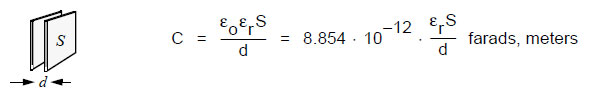
[Figure 1 and most of the other figures in this chapter are reprinted with permission from “Capacitive Sensors,” Larry K. Baxter, IEEE Press, 1997.]
With a plate size of 100 mm x 100 mm and a spacing of 1mm, the capacitance in vacuum, neglecting a small fringe effect, is 88.54 pF.
With a vacuum dielectric, the relative dielectric constant er or K is 1. An air dielectric increases K to 1.0006. Typical dielectric materials such as plastic or oil have dielectric constants of 3-10, and some polar fluids such as water have dielectric constants of 50 or more.
Effect of fringing flux
If the plates are close compared to the plate spacing, the calculation in Fig. 1 is accurate. But as the plate spacing increases relative to area, more flux lines connect from the edges and backs of the plates and the measured capacitance can be much larger than calculated.
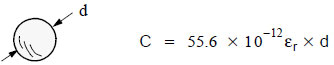
Some other simple geometries are
Figure 2 Disk
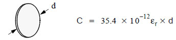
Figure 3 Sphere
Capacitive Sensors
Figure 4 Coaxial cylinders
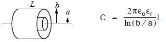
Capacitance of arbitrary electrode shapes
The task of calculating the capacitance of an arbitrary electrode configuration involves finding an integration of Poisson’s Law over the volume of interest. Simple configurations with radial or rectangular symmetry can usually be solved--the solutions above are symmetric--but more complex shapes can be difficult.
For asymmetric electrodes, approximate solutions are available. Field line sketching can produce an approximation of the orthogonal equipotential surfaces and flux lines, and capacitance is estimated by counting squares of the resulting sketch.
Finite Element Analysis software available from Ansoft and others performs a rough equivalent to field line sketching. FEA programs can produce field line drawings in 2D or 3D as well as capacitance values accurate to a percent or less.
3 Motion detection
Direct motion applications are common, with capacitive sensors used for non-contact measurement of angle, long-throw linear displacement, and sub-micron plate spacing.
Several different arrangements of sensing electrodes are used, depending on the measurement job. For accurate measurement of small displacements, spacing variation is best, and for long throw applications, area variation is best. Three-electrode systems can improve performance, and many plates are used in parallel to increase capacitance. Multiple plates can be independently addressed to allow digital readout for better accuracy in long-throw applications.
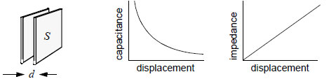
3.1 Spacing variation
Spacing variation of parallel plates is often used for motion detection if the spacing change is less than the electrode size. The parallel plate capacitance formula shows that capacitance is inversely related to spacing. This gives a conveniently large value of capacitance at small spacing, but it does often require signal conditioning which can compensate for the parabolic capacitance-motion relationship. This is easily done by measuring impedance rather than capacitance.
Figure 5 Spacing variation
Several sources of nonlinearity corrupt the performance of a simple parallel plate sensor. A simple
two-plate Z-axis sensor with same-sized plates will have unwanted sensitivity to
• Transverse displacement in X or Y axes
Capacitive Sensors
• Coupling from back of plate
• Tilt
Transverse displacement sensitivity is easily handled by overlap or underlap
Figure 6 Overlap, underlap

Coupling from the back side can be handled with a shield. The shield needs to be driven by the signal conditioning circuit to the same potential as the sense plate so it does not contribute to the measured capacitance. If, for example, the back plate above is driven by a signal source and the front plate is connected to a low-impedance (virtual ground) amplifier, the shield should be connected to ground. Then, only the interplate capacitance contributes to the amplifier output signal.
3.2 Area variation
In the spacing-variation motion detectors above, when displacement increases to the dimension of the electrodes, measurement accuracy suffers from vanishing signal level. Area variation is then preferred.
Figure 7 Area variation
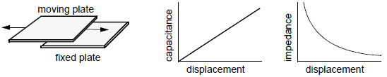
As these plates slide transversely, capacitance changes linearly with motion. Quite long excursions are possible with good linearity, but the gap needs to be small and well-controlled. As with spacing variation, overlap is needed so that unwanted sensitivities are minimized. Here, the unwanted sensitivities are
• Tilt in any axis
• Gap change
• Coupling from back of plate
Several methods help with tilt sensitivity, such as using a small pickup plate with a chevronshaped driven plate
Capacitive Sensors
Figure 8 Chevron shape to combat tilt
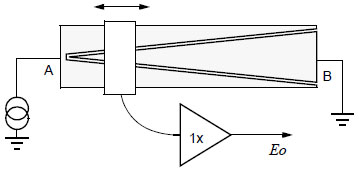
The rectangular pickup plate moves laterally above the chevron, and it is spaced with a small (about 0.5 mm) gap. The chevron plates are driven with a signal voltage of, say, 5 V at 100 kHz, and a high-impedance 1X amplifier is used. The amplifier output Eo varies linearly from 5 V at the left side to 0 at the right side, and the output voltage is insensitive to pickup plate tilt and displacement in the vertical dimension. The Eo vs. displacement curve is nonlinear, but can be linearized by appropriate shaping of the electrodes [Baxter, 1997, p. 91].
3.3 Three plate systems
Adding a third electrode helps in several ways
Figure 9 Third electrode
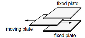
• Sensor capacitance is doubled
• Tilt is first-order compensated
• Shielding is easier
The three-plate sensor can be used for either spacing-variation or area-variation sensors.With a two-plate sensor, the sensor capacitance is the measured variable. Any circuit which measures this capacitance will produce a ratio of the sensor capacitance to a discrete circuit element, a fixed capacitor or resistor.
With three-plate sensors, two capacitances are formed, C1 between top and center plate and C2 between center and bottom plate. The amplifier circuit, depending on its configuration, can generate a voltage proportional to C1 - C2 or C1/C2 or (C1 - C2)/(C1 + C2). This makes ratiometric measurements possible, where one capacitor is variable with motion and the other is fixed. Then the ratio C1/C2 or (C1 - C2)/(C1 + C2) can be arranged to track with temperature, first-order compensating for thermal expansion effects and compensating the small changes in air dielectric
constants with humidity or pressure.
3.4 Multiple plate systems
Capacitive Sensors
Parallel
Parallel multiplates can to increase the sensor capacitance in a small volume
Figure 10 Parallel multiplates
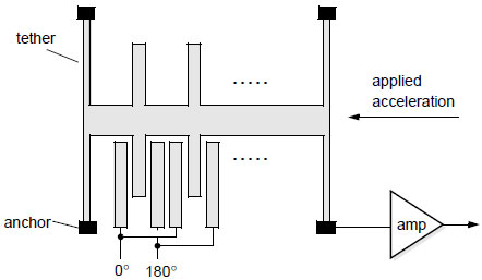
This figure shows the electrode structure of Analog Devices’ surface-machined silicon accelerometer, the ADXL50, with an overall size of 500 x 625 mm. Its 42 silicon fingers are 100 mm in length with a 2 mm gap and a total capacitance of 0.1 pF. The H-shaped piece is elastically mounted using the good spring characteristics of silicon, and responds to acceleration in the x direction with a small displacement. With a displacement in the -x axis, the H picks up more of the 0 deg. drive signal, and a demodulator (not shown) converts the displacement into acceleration.
As the limiting resolution of the sense amplifier is 20x10-18 pF, a beam displacement of 20x10-12 m can be measured.
Independent multiplates
Despite the high accuracy of capacitance motion detection, system imperfections such as mechanical tolerance, unwanted tilt sensitivity and residual analog circuit accuracy limit the reasonable performance of a simple analog sensor to about 0.1% accuracy. For some applications, such as a digital vernier caliper manufactured by L.S. Starrett Co., an 0.0001" resolution over 6" was needed. This multiplate pattern was used
Capacitive Sensors
Figure 11 Multiplate electrodes
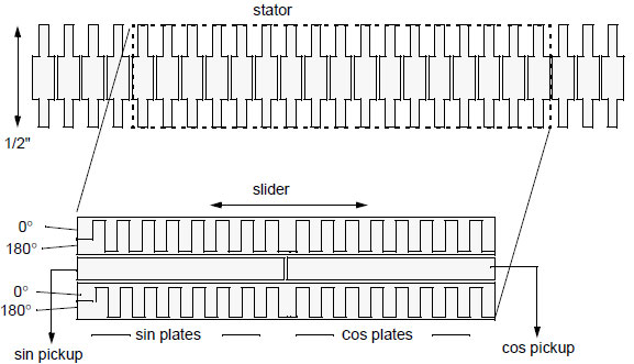
The stator pattern shown is fabricated on the top copper layer of a standard glass-epoxy laminate and glued to the stainless steel bar of the caliper. The slider pattern is similarly fabricated on PC laminate, drives a 100 kHz signal through the sin/cos plates to the stator electrodes, and picks up AC voltages at the two central pickup plates which describe sin(displacement) and cos(displacement) signals. Separate sin and cos signals are needed as in rotary encoders to determine direction of motion. The capacitive coupling of the drive signals substitutes for a wire
connection.
The combination of plate-counting digital circuits and analog interpolation between plates yields 0.0002” accuracy over 6 " with standard PC fabrication methods.
This application uses a small watch battery, and shows the microamp-level current consumption
possible with the technology.
3.5 Rotary motion sensors
The examples above all show linear motion transducers, but many capacitive sensors are used for rotary motion. Rotary motion electrode design is simply done by wrapping the single-plate or multiplate patterns around 360 degrees. Just as tilt and offset in a single-plate motion pickup must be addressed with correct plate design (fig 8), tilt or runout in a rotary transducer is handled with the same techniques.
The use of indepently addressed multiplates in rotary encoders is common. Very high accuracy electrodes can be manufactured with thin film deposition on glass and precision photolithography, with feature sizes down to 5 mm lines and spaces.
3.6 2D sensors
A variety of two-dimensional capacitive sensors have been produced, including this finger-position sensor
Capacitive Sensors
Figure 12 Finger position sensor
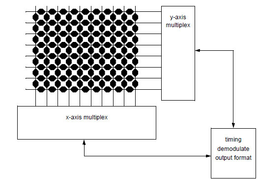
This device, often found just in front of the keyboard on a laptop computer, drives a pulse in succession on each column and measures coupling to each row. By locating the coordinates of peak coupling and interpolating between adjacent rows, the location of a shielding human finger is measured to a fraction of a mm.
4 Sensing of other variables
Capacitive sensors directly sense electrode motion, conductive or dielectric object motion, or the dielectric properties of a local material. All other variables must be first converted into one of these.
As the technology is capable of excellent, stable, low-noise sensing, this indirect method works well. As an example, a cube of brass one cm square expands sufficiently with temperature to make a good thermometer, with better than one degree C accuracy. An infrared imager has been built which converts IR energy into the displacement of thousands of small (14 mm) bimetallic strips which are read capacitively.
Figure 13 Equivalent circuit
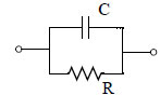
The equivalent circuit of a capacitor can be approximated by this circuit, with small series resistance and inductance neglected for our high-impedance uses. Good capacitor dielectrics have a very large shunt resistance; polypropylene capacitors have an RC product of over 300 hours. Other materials have a much smaller shunt resistance, sometimes reaching 5-10% of the impedtiming
Capacitive Sensors
ance of the capacitor. Although the dielectric constant K of most materials is stable, the shunt resistance or its equivalent, loss tangent, may show considerable variation with material properties or with frequency.
As an example, dry leather has a loss tangent of 0.045, but with a relative humidity of 15% the loss tangent increases to 1.4--possibly a good hygrometer. Aviation gas at 100 octane exhibits a loss tangent at 1 kHz of 0.0001, but at 91 octane loss tangent increases to 0.0004.
Water has a high K (80) and a loss tangent which peaks at low frequencies and again at 1010 Hz. With this high dielectric activity, the loss tangent or the dielectric constant of water can be used to detect the moisture content of materials.
Another characteristic of capacitor dielectrics which may have some use in detecting material properties is dielectric absorption. It is measured by charging a capacitor, discharging for 10 s, and measuring the charge which reappears after 15 min. A relatively low-quality dielectric like metallized paper has a dielectric absorption of 10%.
5 Signal conditioning
Signal conditioning circuits convert capacitance variations into a voltage, frequency, or pulse width modulation. Very simple circuits can be used, but simple circuits may be affected by leakage or stray capacitance, and may not be suitable for applications with very small capacitance sense electrodes.
5.1 Excitation frequency
The excitation frequency should be reasonably high so that electrode impedance is as low as possible. Typical electrode impedance is 1-100M ohms. Ideally, the excitation frequency will be high enough to reject coupling to power waveforms and also high enough so that the overall sensor frequency response is adequate; about 50 kHz is usually acceptably high. The frequency should also be low enough for easy circuit design, CMOS switches work well at 100 kHz and below.
Excitation waveshape is usually square or trapezoidal, but a triangle waveform can be used to allow a simpler amplifier with resistive feedback and a sine wave offers better accuracy at high frequency. Square wave excitation produces an output bandwidth which can be higher than the excitation frequency by 10x or more, other waveshapes usually result in an output bandwidth 2x or 3x lower than the excitation frequency.
Sensors excited with a continuous wave signal usually use synchronous demodulators. This demodulator type offers high precision and good rejection of out-of-band interference.
5.2 Pulse operation
A single pulse can be used to sample a variable capacitor, like a microcomputer read pulse, or a train of pulses can be used. This method can result in simpler electronics but will have higher noise.
5.3 Oscillator
An R-C relaxation oscillator such as the venerable 555 or its CMOS update, the 7555, converts capacitance change into a change of frequency or pulse width.
Capacitive Sensors
Figure 14 RC oscillator
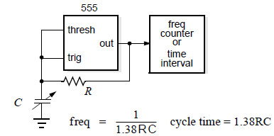
The RC oscillator used with a spacing-variation capacitor will produce a frequency output which is linear with spacing, while an area-variation capacitor is linearized by measuring pulse width.
The circuit as shown has no way of accommodating stray capacitance. If, for example, the capacitor is connected by a coaxial cable, the cable capacitance adds to the measured capacitance and spoils stability and sensitivity. Often a computer can be used to calibrate these errors, but the synchronous demodulator circuits shown below are a more accurate choice.
Another drawback with the RC oscillator is that capacitance is measured relative to the fixed resistor, and the resistor stability and temperature coefficient may not track well.
Synchronous demodulators allow the use of capacitance bridges so the reference capacitance tempco will track accurately, yielding higher accuracy sensors.
5.4 Simple circuit
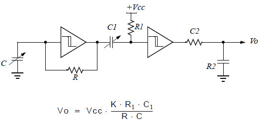
This circuit uses a CMOS schmitt inverter as an RC oscillator followed by a oneshot R1C1 (with a smaller time constant) followed by lowpass R2C2 (with a larger time constant). The output can be either capacitance-linear or 1/capacitance linear, depending on the location of the sense capacitor. It is, unfortunately, not particularly stable with temperature and power supply and it may require a floating sense capacitor.
5.5 Synchronous demodulator circuits
Capacitive Sensors
Figure 15 Sync demodulator
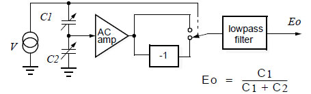
A square wave excitation voltage V at 5 V p-p feeds the variable capacitance (C1, C2, or both may be variable) and also a CMOS switch. A high-impedance unity-gain AC amplifier feeds the switch directly and also feeds an inverter. If the phase shift through the amplifier is low, the switch output is an accurate demodulation, probably contaminated by narrow spikes caused by switching transients. These transients are eliminated in the lowpass filter.
An advantage of the synchronous demodulator is that out-of-band signal components are eliminated in the lowpass filter. This is important in applications where power line harmonics or other crosstalk contaminate the signal.
Figure 16 Feedback around AC amplifier
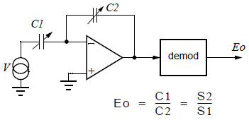
The amplifier is now a low-input-impedance or virtual ground type. The circuit is incomplete, needing some method of controlling the DC bias on the amplifier input, usually handled by a large-value resistor across C2. The circuit can linearize either type of motion sensor--the output will be linear with motion if C2 is a spacing-variation capacitor , or if C1 is an area-variation capacitor.
Note that a grounded shield surrounding the amplifier’s inverting input can shield the circuit from extraneous fields but its added capacitance will not affect the output voltage, except perhaps by slowing amplifier frequency response.
Capacitive Sensors
Figure 17 Feedback around demodulator
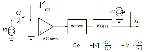
This circuit has several advantages over the circuit above (fig 15). The amplifier output can be at a low level, easing slew rate problems. And if V1-C1 and V2-C2 are implemented with matching components, the temperature coefficient will track. The demodulator is now included inside the loop and can be nonlinear without much effect on overall accuracy. A SPDT CMOS switch such as Maxim’s MAX4544 can be used for V1 and V2, with excellent stability and accuracy, better than 0.1%.
Square wave source V1 drives the bridge and the demodulator. The AC amplifier should have low current noise. KG(s), which may be an integrator, provides DC gain and should have a zero cross frequency about 10x lower than the excitation frequency for stability. Its output, DC signal output Eo, is also used to generate an amplitude-variable AC signal at V2. V2’s output feeds back to the AC amplifier, and with correct stabilization at KG(s), the circuit settles with the input to the AC amplifier nulled.
Other system components can be included in the feedback loop. In a mechanical positioning system using a solenoid drive and a capacitance sensor, for example, the output of KG(s) could drive a solenoid, with V2 used as a position command. Then the nonlinearities of the solenoid drive are included in the loop and have much less effect. Another possibility for digital systems is to replace the KG(s) block with an up-down counter and a DAC, so the system has a digital output instead of analog.
A complication with this circuit if the variable capacitor has wide range is that the closed-loop gain changes radically over the sensor range. This causes one end of the range to exhibit a sluggish, overdamped response. This problem disappears if C2 is a fixed capacitor and C1 variable, or if V1 as well as V2 is controlled by the output voltage.
A frequent problem with this circuit is the need for floating sense capacitors. Since ground is a rather ephemeral concept, the aggressive analog engineer may say, “Aha! No problem. Simply move your circuit ground to the connection betwen sense capacitors.” Indeed, this will allow grounded sense capacitors, but it will result in floating power supplies and floating variable voltage generators. When the dust settles down, your tiny low-capacitance sense node has grown large and includes power supplies, etc., and picks up a lot of parasitic capacitance. And parasitic
sense node capacitance (see “Noise” on page 15) increases noise and hurts amplifier frequency response.
6 Hazards
The high impedance capacitive sensor needs special handling compared to other sensor types, and several possible sources of sub-microampere DC or AC signals which couple to the amplifier input must be prevented.
Capacitive Sensors 13
6.1 Leakage
Small sensor plates can have an impedance of many megohms, and amplifier input impedance and leakage should be many hundreds of megohms for good accuracy. Leakage paths on the printed circuit board are usually on the surface, and can be caused by
• Rosin residue or lubricant collecting airborne impurities
• Conductive residue from water-base cleaning fluids
• Paint, pigmented with carbon
• High humidity
Guarding against leakage
Surface leakage can be combatted by guarding. A typical high-impedance guarded amplifier is shown
Figure 18 Guarding leakage paths, low-Z amplifier
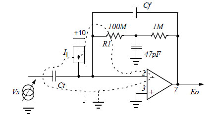
The op amp input bias current may be as low as 10 fA. Leakage current caused by surface leakage resistance of 1015 ohms will equal the operational amplifier’s bias current and can force the amplifier output to a rail.
Careful cleaning or conformal coating will help, but a simple guarding techniwue is best. Surface guarding interrupts leakage paths. with a grounded printed circuit trace, shown above as a dotted line. Solder mask over the guard trace conducts surface currents over the guard, so solder mask should be relieved over the guard foil.
6.2 Static charge
Static charge can build up on the insulators near capacitive sense plates due to triboelectric charging, causing a tiny spark in serious cases. In less serious cases, a charge buildup of 50-100 V will not arc over but can cause an unwanted sensitivity to mechanical vibration. This sensitivity results from the voltage V = Q/C caused by constant capacitor charge and a capacitance which varies with spacing change due to vibration and can drive the amplifier input over its rails.
To reduce static charge
• Raise the humidity. The surface leakage resistance of almost all insulators is is a strong function of humidity. With RH 20% and higher, a little surface leakage drains
Capacitive Sensors
off the charge.
• Redesign the circuit. With a low-input-impedance AC amplifier, the over-the-rails problem can be handled, and the signal processing electronics can be designed to ignore a single large transient
• Use bare metal plates. Bare metal will not have triboelectric-effect static discharge problems. Corrosion of bare copper is minimized by use of a corrosion-resistant metal plating such as nickel or gold over nickel
• Use a higher frequency carrier. Mechanical vibrations and resonances are usually in a low frequency range, below 10 kHz. A 100 kHz carrier and a a highpass filter will minimize mechanical resonance and static charge effects
6.3 Noise
The limit to the signal-to-noise ratio of capacitive sensors is the ratio of excitation voltage to amplifier voltage noise. For best signal to noise ratio the excitation voltage can be 5-500 V and a high-impedance amplifier can have voltage noise of one or two nVper root Hz. This provides a signal-to-noise ratio of 2x10⁹ to 5x10¹¹ in a 1 Hz bandwidth. This theoretic limit will be degraded if amplifier current noise becomes a factor, as with very high impedance sensors, or if amplifier input capacitance is larger than sensor capacitance. The lowest noise is achieved with a JFET amplifier (or an op amp with JFET input stages) and with the JFET input capacitance equal to the sensor capacitance.
7 Stability
Capacitive sensors are constructed with two or more conducting electrodes and an insulating support. These components as well as the K of the dielectric medium, usually air, will change in response to environmental factors. With stable materials and careful construction, sensors with a long-term stability of better than one part in 10-9 per day are possible.
7.1 Temperature coefficient
Conductors
Most common metals and alloys have a temperature coefficient of linear expansion in the range of 9-32 mm/m/GHJ#C (5-18 minch/inch/GHJ F). Silicon, at 5 mm/m/GHJ C is quite stable, as well as having excellent spring characteristics.
Thermal expansion will be a limiting factor in the design of very precise capacitive sensors, but it can usually be handled by careful balancing of critical parts and by use of bridges and differential detection.
Insulators
Insulators have a much wider range of thermal expansion than metals. Glass, quartz, and diamond expand between 0.5 and 3.3 ppm/ deg C Plastics vary from polyimide’s 20 ppm/deg C through epoxy’s 45-65 ppm to Teflon’s 100 ppm/deg C..
7.2 Dielectric constant of air
The dielectric constant of air changes slightly with pressure, temperature and humidity. Over a moderate excursion of these variables, we see a change of 170 ppm
Capacitive Sensors
Change in dielectric constant of air
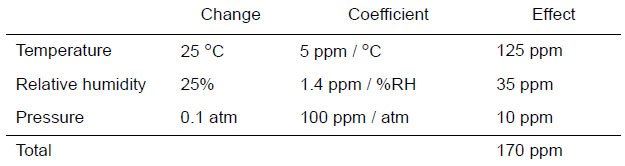
This change can be enough to affect the accuracy of precision detectors, but it can be easily compensated by building a reference capacitor in air with materials similar to the sense capacitor’s and using a balanced bridge detector.
Stability with time
Long-term stability of materials is also a concern for very sensitive applications. Standard bronze meter bars changed in length by 2 ppm in 52-year period. Hard metals like stainless steel and iridium are stable, while light alloys like aluminum are considerably worse.
Stability with humidity
Metals have insignificant water absorption and chemical absorption. Most insulators, however, expand with humidity. Glass, TFE (Teflon™), polyimide (Kapton™), or mica are good choices for humidity-stable insulators.
| |
|
|
|
|
|